

Popular Pages
Today's:
- Information for Authors
- (ISBI 2026) 2026 IEEE 23rd International Symposium on Biomedical Imaging
- (ASRU 2025) 2025 IEEE Automatic Speech Recognition and Understanding Workshop
- What’s Next for Speech Recognition? Explore the Innovations Shaping the Future — New Our Digital Life Podcast Episode
- IEEE Transactions on Information Forensics and Security
- Congratulations to Signal Processing Society Members Elevated to Senior Members!
- IEEE Transactions on Multimedia
- IEEE Transactions on Image Processing
- IEEE Signal Processing Letters
- IEEE Journal of Selected Topics in Signal Processing
- Get Involved with Technical Committees by becoming a TC Affiliate
- Submit a Manuscript
- Unified EDICS
- IEEE Transactions on Audio, Speech and Language Processing
- Call for Nominations for the IEEE Transactions on Medical Imaging (TMI) Best Paper Award
All time:
- Information for Authors
- Submit a Manuscript
- IEEE Transactions on Image Processing
- IEEE Transactions on Information Forensics and Security
- IEEE Transactions on Multimedia
- IEEE Transactions on Audio, Speech and Language Processing
- IEEE Signal Processing Letters
- IEEE Transactions on Signal Processing
- Conferences & Events
- IEEE Journal of Selected Topics in Signal Processing
- Information for Authors-SPL
- Conference Call for Papers
- Signal Processing 101
- IEEE Signal Processing Magazine
- Guidelines
Last viewed:
- (ISBI 2026) 2026 IEEE 23rd International Symposium on Biomedical Imaging
- (ICSM 2025) 2025 International Conference on Smart Multimedia
- Conference Call for Papers
- IEEE Transactions on Multimedia
- IEEE Transactions on Information Forensics and Security
- Scope & Mission
- Awards & Submit Award Nomination
- (ICIP 2025) 2025 IEEE International Conference on Image Processing
- Meeting Minutes
- Subcommittees
- Members
- IFS TC Home
- (ASRU 2025) 2025 IEEE Automatic Speech Recognition and Understanding Workshop
- IEEE JSTSP Special Issue on Advancing Signal Processing Algorithm for Fluid Antenna Systems (FAS)
- Tülay Adali
The Long Journey of a GPS Signal


Top Reasons to Join SPS Today!
1. IEEE Signal Processing Magazine
2. Signal Processing Digital Library*
3. Inside Signal Processing Newsletter
4. SPS Resource Center
5. Career advancement & recognition
6. Discounts on conferences and publications
7. Professional networking
8. Communities for students, young professionals, and women
9. Volunteer opportunities
10. Coming soon! PDH/CEU credits
Click here to learn more.
News and Resources for Members of the IEEE Signal Processing Society
The Long Journey of a GPS Signal
Satellite-based navigation and location technology has become a valuable tool for many positioning, navigation, and timing services. These include both civilian and military applications. Several Global Navigation Satellite Systems (GNSS) are currently fully or partially functional, with the US Global Positioning System (GPS) topping the list and having a constellation of at least 24 satellites operating simultaneously. GLONASS, the Russian system, currently has a global coverage, too. Likewise, the European Union is rapidly growing its own satellite navigation system, Galileo, slated for completion in 2018.
These systems are based on transmitting Radio Frequency (RF) signals in a one-way fashion from satellites to receivers on and near the Earth’s surface. Using these signals, a GNSS receiver can find its position, velocity and time. However, in addition to travelling tens of thousands of kilometers, these signals, like other RF signals, are susceptible to various disruptions and the effects of noise. Thus, the target signals will have been severely weakened by the time they reach the receiver’s antenna, and this makes signal processing problematic.
So far, GPS is the most powerful GNSS; hence, this article tells the fascinating story of the GPS signal’s entire journey, from its beginnings within a satellite’s circuitry all the way through to its processing by a GPS receiver.
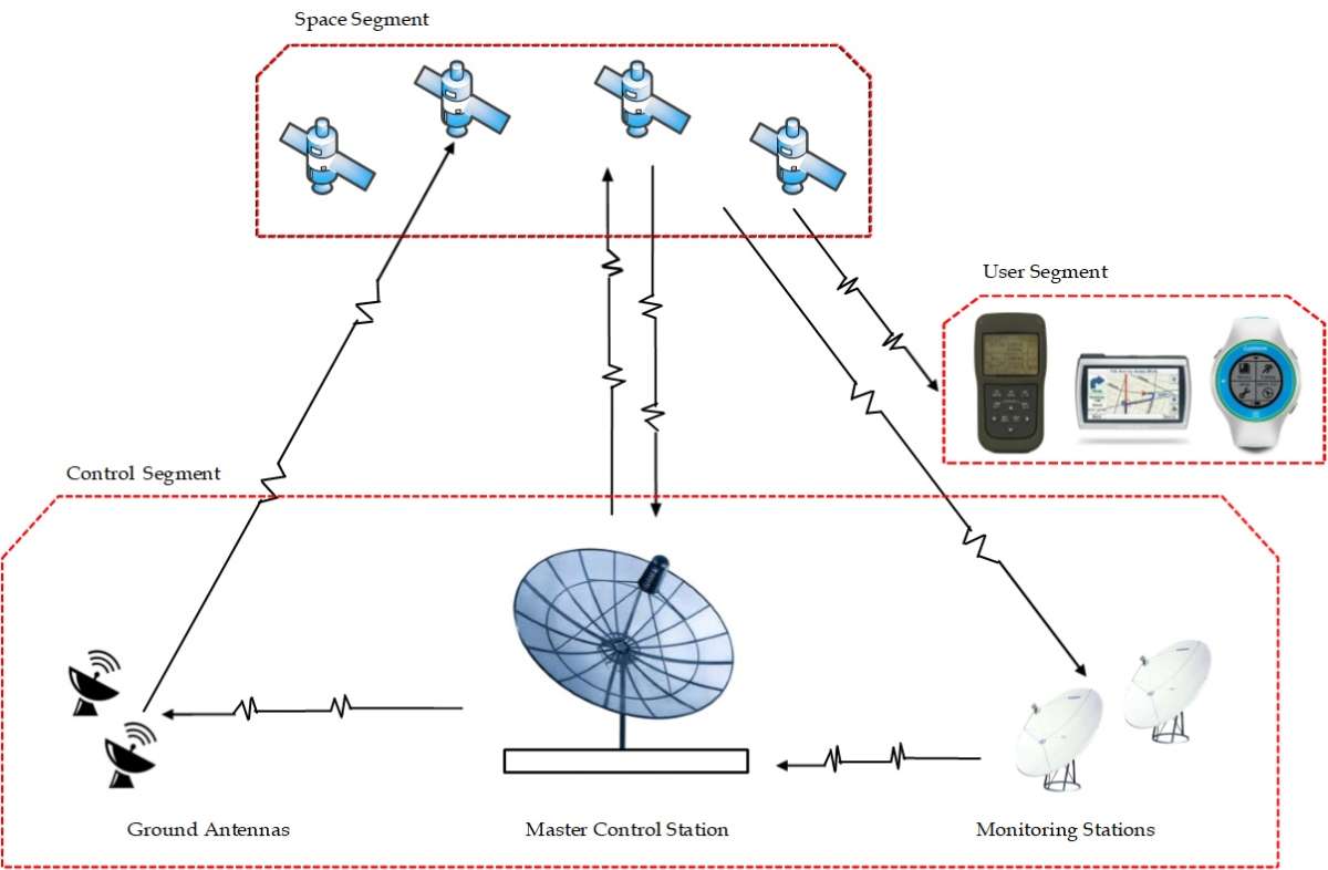
The GPS system is composed of three segments: 1) the space segment, 2) the control segment, and 3) the user segment (Figure 1 illustrates the three GPS segments). The space segment contains the satellite constellation, which is usually made up of 24 to 32 satellites. The control segment is made up of twelve monitoring stations distributed across the world with a master control station in Colorado Springs, United States. The key role of this segment is to upload navigational information and satellite clock corrections to the satellite constellation. As for the user segment, it comprises millions of civilian and military users worldwide with a range of types of GPS receivers.

The GPS signal’s journey starts at an elevation of about 22,000-26,000 km above the Earth inside a satellite travelling at an orbital speed of about 14,000 km/h. To help the signal reach such a distant destination, it is transmitted atop a very high frequency carrier signal. Included in the signal along with a navigation message is a unique code, known as a pseudorandom code, which tells the satellite’s identity. Moreover, the time when the message is sent is marked on the transmitted signal for the receiver to use to measure the range to each satellite. Because exact timing is critical for effective navigation, and positioning and timing services, navigation satellites are equipped with very precise, and hence very expensive, atomic clocks.
Riding atop the carrier signal in the band of radio frequency (RF), the signal leaves the satellite antenna at a power level of only few hundred watts, and after this it travels long distances through a range of mediums. As shown by Figure 2, the first and major part of this trip is through space where the signal maintains its initial characteristics, foremost of which is its constant speed. After this, when it reaches an altitude of about 1,000 km above the Earth’s surface, changes start to occur. At this point, the signal penetrates the upper atmosphere; namely, the ionospheric layer. This layer of atmosphere contains various gases that are easily ionized by the sun’s radiation. While the intensity of solar activity is the decisive factor determining the condition of the ionosphere, this is also affected by season and time-of-day. Accordingly, these three parameters determine the level of ionization, thereby affecting the refractive indices of the various layers of the ionosphere, and hence, influencing the signal transit time measured by the receiver.
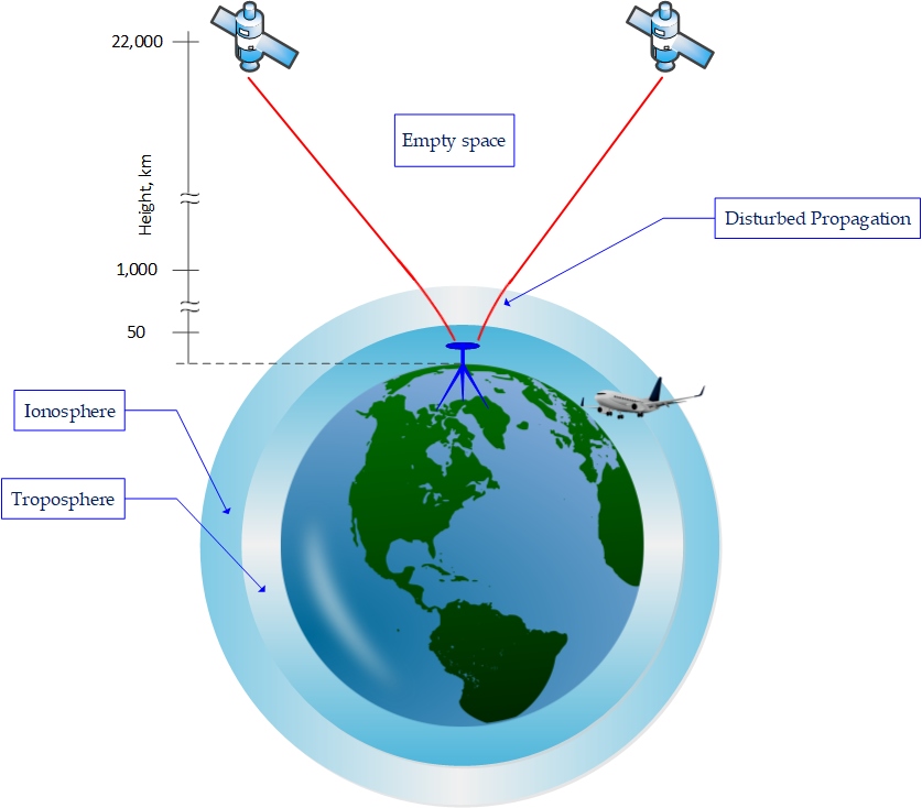
The next step is for the signal to move through the troposphere, the lower part of atmosphere which extends from about 8 km above the Earth’s surface up to about 50 km and is composed of dry gases and water vapor. As a refractive layer, the troposphere, too, delays GPS signals; however, being electrically neutral the layer is non-dispersive for some GPS frequencies. Tropospheric delay has two components, wet and dry. The wet component is difficult to model, but fortunately it accounts for only 10 percent of the delay. The dry component, which is responsible for the rest of the delay, can be more easily modeled. Delays and errors caused by both layers of atmosphere can be modeled and partially removed from the received signal to provide cleaner receiver-tosatellite range measurements.
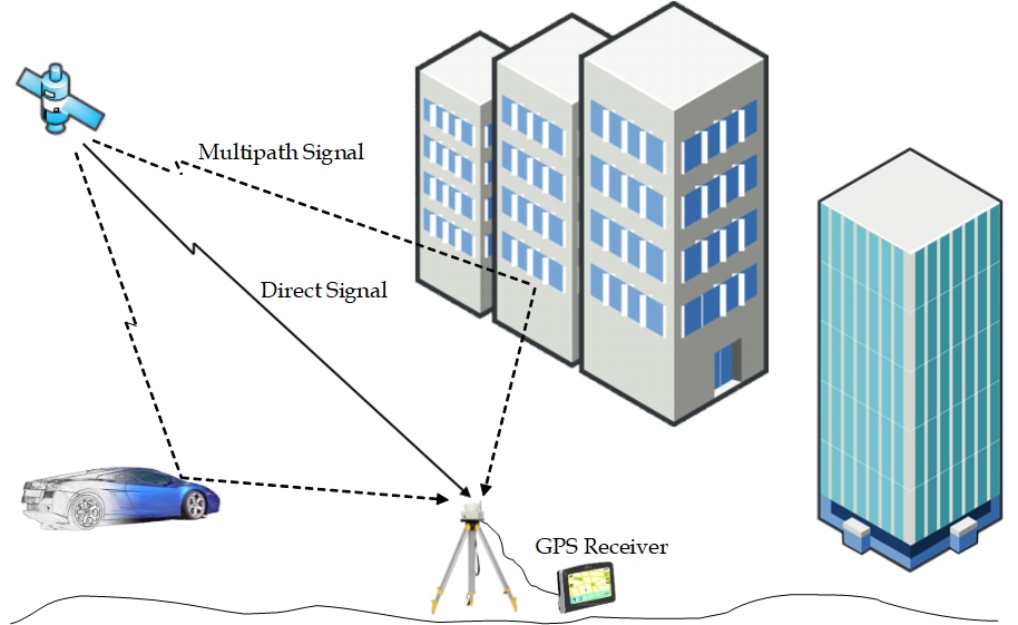
As the signal nears the receiver antenna, it is often further degraded. In several scenarios, the signal may reach the receiver’s antenna via more than one path, owing to signal reflections from surrounding structures or the ground (see Figure 3). Normally, one of the received signals would be the direct line-of-sight signal, along with one or more of its reflections, which are delayed versions of the original signal. This multipath signals’ composition is constructive in instances when the quality of received signal is not affected; however, in most cases, the original signal is distorted through interference by the reflected signals and, consequently, could completely vanish. One solution to avoid this source of error is to place the receiver antenna in a reflectionfree location, but this is not always practical, particularly when the GPS receiver is on a moving platform. Some modern receivers use techniques relying on multiple antenna or what is known as an antenna array. With such technology, the receiver can tune itself to track only the line-of-sight signal and block all other replicas of the signal.
All aforementioned signal disturbances are a result of the nature of the signal or the propagation medium and are considered unintentional. Intentional interference is, however, a major source of RF signal degradation. Known as signal jamming, this interference with other signals in the same band of interest is a growing problem worldwide that effects nearly all electronic equipment using time generated by GNSS receivers. The main direct consequences of jamming are signal frequency shifts in Hertz (Hz) and drop in signal power, as measured in Decibels (dB). These effects, in turn, cause further difficulties, foremost of which are receiver clock drift in seconds/seconds, velocity errors in meters/seconds (m/s), and position errors in meters (m). Other aspects of jamming that are of concern to users are the length of an incident, as expressed in units of time, or how the size of the affected area.
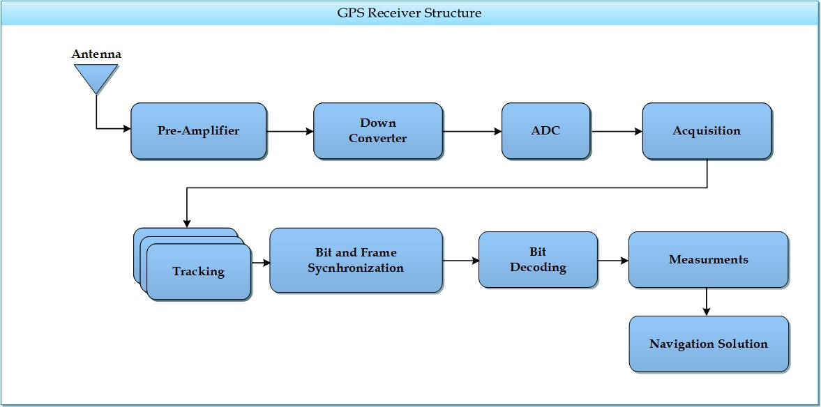
To be ready for processing, the signal will still need to travel a few more centimeters inside the receiver through several units including preamplifiers, frequency-down converters, and analog-to-digital converters (ADCs). Because the signal is very weak when it reaches the receiver antenna, the amplifiers are needed to make the signal strong enough for the receiver circuitry to process it. As for the frequency-down converters, these lower the very high-frequency carrier signal on which the signal rides, bringing it down to a reasonable range. At this stage, the signal is still in the analogue or continuous form; the ADC unit converts the signal into a digitized stream of samples that are fed into the next circuitry in the form of binary bits.
This last part of the journey causes further loss to signal power. Low power, in turn, results in a low signal-to-noise ration (SNR), especially when a large filter bandwidth is used, and this received power cannot be improved at the transmitter’s end. Increasing transmitted power, or transmitter antenna gain, clearly demands higher power consumption, perhaps a larger antenna, and, consequently, would increase costs. Lowering the frequency is not possible for two reasons. First, GPS is assigned a specific band in the radio frequency spectrum. Secondly, lower frequencies are not valid for space-to-earth signaling owing to the characteristics of the transmission media. Thus, the receiver needs to deal with these power levels “as is” and have tracking mechanisms able to handle this challenge.
The GPS receiver is one of the most sophisticated communication systems on the planet: within a fraction of a second, the GPS signal makes its entire journey between the satellite circuitry and receiver components to deliver the navigation data -- a message with which a user can find its location, speed, and time.
Author: Malek Karaim is a Ph.D. student and a teaching fellow at the Department of Electrical and Computer Engineering, Queen’s university, Canada. He is working within the Navigation and Instrumentation Research (NavINST) Group at Queens’ University/Royal Military College of Canada. His research focus is on GPS signal vector tracking, ultra-tight GPS/INS integration, and GPS software receiver design.
Open Calls
SPS Social Media
- IEEE SPS Facebook Page https://www.facebook.com/ieeeSPS
- IEEE SPS X Page https://x.com/IEEEsps
- IEEE SPS Instagram Page https://www.instagram.com/ieeesps/?hl=en
- IEEE SPS LinkedIn Page https://www.linkedin.com/company/ieeesps/
- IEEE SPS YouTube Channel https://www.youtube.com/ieeeSPS
IEEE SPS Educational Resources
IEEE SPS Resource Center

IEEE SPS YouTube Channel